IMMUNITY TESTING
Conducted RF Test
The source of disturbance covered by this test is basically an electromagnetic field, coming from intended RF transmitters, that may act on the whole length of cables connected to an installed equipment. The dimensions of the disturbed equipment, mostly a sub-part of a larger system, are assumed to be small compared with the wavelengths involved. The in-going and out-going leads: e.g. mains, communication lines, interface cables, behave as passive receiving antenna networks because they can be several wavelengths long.
Between those cable networks, the susceptible equipment is exposed to currents flowing "through" the equipment. Cable systems connected to an equipment are assumed to be in resonant mode (l /4, l /2 open or folded dipoles) and as such are represented by coupling and decoupling devices having common-mode impedance or 150W with respect to a ground reference plane.
This test subjects the EUT to a source of disturbance comprising electric and magnetic fields, simulating those coming from intentional RF transmitters. These disturbing fields (E and H) are approximated by the electric and magnetic near-fields resulting from the voltages and currents caused by the test set-up.
The EUT is subjected to an electromotive force (e.m.f.) of 3 V or 10 V from 150 kHz to 80 MHz. This frequency range is 80% amplitude modulated with a 1 kHz sine wave. The signal generator provides the modulated frequency at a step rate of 1% of fundamental to the RF amplifier. The dwell time at each frequency is not less than the time necessary for the EUT to be exercised, and able to respond. Clamp injection on all cables of the EUT is used to couple the e.m.f. to the EUT.
No tests are required for induced disturbances caused by electromagnetic fields coming from intentional RF transmitters in the frequency range 9 kHz to 150 kHz.
| Frequency Range: 150 kHz to 80 MHz Test Levels | ||
| Level | Voltage level (e.m.f.) | |
| Uo [dB(m V)] | Uo [V] | |
| 1 | 120 | 1 |
| 2 | 130 | 3 |
| 3 | 140 | 10 |
| X | Special | |
"X" is an open test level. | ||
Conducted RF TEST SETUP From : 61000-4-6 . IEC:2003
7 Test set-up for table-top and floor-standing equipment
The equipment to be tested is placed on an insulating support of 0,1 m height above a ground reference plane. All cables exiting the EUT shall be supported at a height of at least 30 mm above the ground reference plane.
If the equipment is designed to be mounted in a panel, rack or cabinet, then it shall be tested in this configuration. When a means is required to support the test sample, such support shall be constructed of a non-metallic, non-conducting material. Grounding of the equipment shall be consistent with the manufacturer’s installation instructions.
Where coupling and/or decoupling devices are required, they shall be located between 0,1 m and 0,3 m from the EUT. This distance is to be measured horizontally from the projection of the EUT on to the ground reference plane to the coupling and/or decoupling device. See Figures 6, 9 and 10. Subclauses 7.1 to 7.7 provide more detailed information.
7.1 Rules for selecting injection methods and test points
For selecting the type and number of cables to be provided with coupling and decoupling devices, the physical configuration of typical installation conditions shall be considered, e.g. the likely length of the longest cables.
For all tests, the total cable length between the EUT and AE (including the internal cabling of any CDN being used) shall not exceed the maximum length specified by the manufacturer of the EUT.
7.1.1 Injection method
Figure 1 gives rules for selecting the injection method.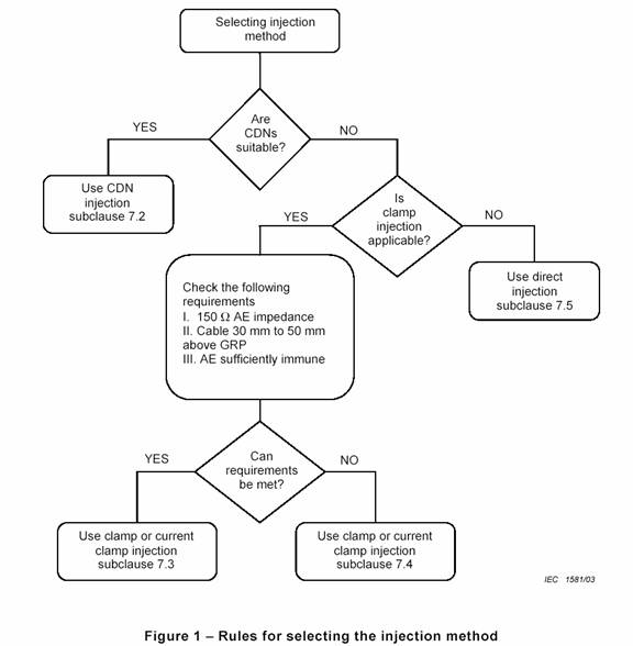
Where not specified herein, the EUT including selected cables for testing shall be configured, installed, arranged and operated in a manner consistent with typical applications. CDNS not listed in this standard, but meeting the requirements of this standard, may also be used.
When several cables coming from the EUT are in close proximity over a length of more than 10 m or are routed from the EUT to another equipment in a cable tray or conduit, they should be treated as one cable.
If a product committee decides that a certain kind of coupling and decoupling device is more appropriate for cables connected to a particular family of products, then that choice (justified on a technical basis) takes precedence. These devices shall be described in the product standard. Examples of CDNs are described in Annex D.
7.1.2 Ports to be tested
In any one test, only two 150 ? networks are required. The network used for injection of the test signal can be moved between different ports as they are tested. When a CDN is removed from a port, it may be replaced by a decoupling network.
If the EUT has multiple identical ports (same input or output electronic circuits, loads, connected equipment, etc.), at least one of these ports shall be selected for testing to ensure that all different types of ports are covered.
7.2 Procedure for CDN injection application
When using the CDN injection, the following measures need to be taken.
• If the AE is located above the GRP, then it is to be placed 0,1 m above the GRP.
• One CDN shall be connected to the port intended to be tested and one CDN with 50 W termination shall be connected to another port. Decoupling networks shall be installed on all other ports to which cables are attached. In this manner there is only one loop terminated with 150 W at each end.
• The CDN to be terminated shall be chosen according to the following priority:
| 1) | CDN-M1 used for connection of the earth terminal; |
| 2) | CDN-Sn (n = 1,2,3,..), which is closest to the injection point (shortest geometrical distance to the tested port); |
| 3) | CDN-M2, CDN-M3, CDN-M4, or CDN-M5 used for mains; |
| 4) | Other CDN, which is closest to the injection point (shortest geometrical distance to the tested port). |
• If at least one AE is connected to the EUT and only one CDN can be connected to the EUT, one port of the AE shall be connected to a CDN terminated with 50 W in accordance with the above-mentioned priority and other connections to the AE shall be decoupled.
7.3 Procedure for clamp injection when the common-mode impedance requirements can be met
When using clamp injection, the AE set-up shall present the common-mode impedance as required in 6.2 as closely as possible. Each AE used with clamp injection shall represent the functional installation conditions as closely as possible. To approximate the required common-mode impedance the following measures need to be taken.
• Each AE, used with clamp injection, shall be placed on an insulating support 0,1 m above the ground reference plane.
• A decoupling network shall be installed on each cable between the EUT and AE except the cable under test.
• All cables connected to each AE, other than those being connected to the EUT, shall be provided with decoupling networks, see 6.2.4 and Figure 6.
• The decoupling networks connected to each AE (except those on cables between the EUT and AE) shall be applied no further than 0,3 m from the AE. The cable(s) between the AE and the decoupling network (s) or in between the AE and the injection clamp shall not be bundled nor wrapped and shall be kept between 30 mm and 50 mm above the ground reference plane (Figure 6).
• At one end of the cable under test is the EUT, and at the opposite end is the AE. Multiple CDNs can be connected to the EUT and to the AE; however, only one CDN on each of the EUT and AE shall be terminated in 50 ?. The termination of the CDN shall be chosen according to the priority in 7.2.
• When several clamps are used, the injection is carried out on each cable selected for testing one by one. The cables which are selected for testing with the injection clamp but not actually exercised shall be decoupled in accordance with 6.2.4.
In all other cases the procedure given in 7.4 should be followed.
7.4 Procedure for clamp injection when the common-mode impedance requirements cannot be met
When using clamp injection and the common-mode impedance requirements cannot be met at the AE side, it is necessary that the common-mode impedance of the AE be less than or equal to the common-mode impedance of the EUT port being tested. If not, measures shall be taken (e.g. by using a CDN-M1 or 150 ? resistor from the AE to ground) at the AE port to satisfy this condition and to prevent resonances. In this procedure, only the relevant differences with those measures mentioned in 7.3 are given.
– Each AE and EUT used with clamp injection shall represent the functional installation conditions as closely as possible, e.g. the EUT shall either be connected to the ground reference plane or placed on an insulating support (see Figures A.6 and A.7).
– By means of an extra current probe (having low insertion loss), inserted in between the injection clamp and the EUT, the current resulting from the induced voltage (set according to 6.4.1) shall be monitored. If the current exceeds the nominal circuit value Imax given below, the test generator level shall be reduced until the measured current is equal to the Imax value:
Imax = U0/150 W
The modified test voltage level applied shall be recorded in the test report.
To ensure reproducibility, the test set-up shall be fully described in the test report.
7.5 Procedure for direct injection
When using direct injection to screened cables, the following measures need to be taken.
• The EUT shall be placed on an insulating support of 0,1 m height above the ground reference plane.
• On the cable being tested, a decoupling network shall be located between the injection point and the AE, as close as possible to the injection point. A second port shall be loaded with 150 W (CDN with 50 W termination) This port shall be chosen according to the priority in 7.2. On all other cables attached to the EUT decoupling networks shall be installed. (When left open, a CDN is considered a decoupling network.)
• The injection point shall be located between 0,1 and 0,3 m from the geometric projection of the EUT on to the ground reference plane.
• The test signal shall be injected directly on to the shield of the cable through a 100 W resistor (see 6.2.3).
NOTE When making direct connection to foil shields, caution needs to be exercised to ensure a good connection producing reliable test results.
7.6 EUT comprising a single unit
The EUT shall be placed on an insulating support 0,1 m above the ground reference plane. For table-top equipment, the ground reference plane may be placed on a table (see Figure 9).
On all cables to be tested, coupling and decoupling devices shall be inserted (see 7.1.2). The coupling and decoupling devices shall be placed on the ground reference plane, making direct contact with it at a distance of 0,1 m to 0,3 m from the EUT. The cables between the coupling and decoupling devices and the EUT shall be as short as possible and shall not be bundled or wrapped. Their height above the ground reference plane shall be between 30 mm and 50 mm.
If the EUT is provided with other earth terminals, they shall, when allowed, be connected to the ground reference plane through the coupling and decoupling network CDN-M1, see 6.2.1.1 (i.e. the AE port of the CDN-M1 is then connected to the ground reference plane).
If the EUT is provided with a keyboard or hand-held accessory, then the artificial hand shall be placed on this keyboard or wrapped around the accessory and connected to the ground reference plane.
Auxiliary equipment (AE) required for the defined operation of the EUT according to the specifications of the product committee, e.g. communication equipment, modem, printer, sensor, etc., as well as auxiliary equipment necessary for ensuring any data transfer and assessment of the functions, shall be connected to the EUT through coupling and/or decoupling devices. As far as possible, the number of cables to be tested may be limited; however, all types of physical ports should be submitted to injection.
7.7 EUT comprising several units
Equipment comprising several units, which are interconnected, shall be tested using one of the following methods.
• Preferred method: Each sub-unit shall be treated and tested separately as an EUT (see 7.6), considering all others as AE. Coupling and decoupling devices (or CDNs) shall be placed on the cables (according to 7.1) of the sub-units considered as the EUT. All subunits shall be tested in turn.
• Alternative method: Sub-units that are always connected together by short cables, i.e. ≤1 m, and that are part of the equipment to be tested, can be considered as one EUT. No conducted immunity test shall be performed on their interconnecting cables, these cables being regarded as internal cables of the system. See Figure 10.
The units being part of such an EUT shall be placed as close as possible to each other without making contact, all on the insulating support 0,1 m above the ground reference plane. The interconnecting cables of these units shall also be placed on the insulating support. Unterminated CDNs or decoupling devices shall be placed on all other cables of the EUT, e.g. on cables to the mains supply and auxiliary equipment (see 7.1).