IMMUNITY TESTING
Surge Test
These tests relate to the immunity requirements for equipment to unidirectional surges caused by overvoltages from switching and lightning transients. Several test levels are defined which relate to different environment and installation conditions. These requirements are developed for and are applicable to electrical and electronic equipment.
System switching transients can be separated into transients associated with :
Major power system switching disturbances, such as capacitor bank switching;
Minor switching activity near the instrumentation or load changes in the power distribution system;
Resonating circuits associated with switching devices, such as thyristors;
Various system faults, such as short circuits and arcing faults to the earthing system of the installation.
The major mechanisms by which lightning produced surge voltages are the following :
A direct lightning stroke to an external circuit (outdoor) injecting high currents producing voltages by either flowing through earth resistance of flowing through the impedance of the external circuit;
An indirect lightning stroke (i.e. a stroke between or within clouds or to nearby objects which produces electromagnetic fields) that induces voltages/currents on the conductors outside and/or inside a building;
Lightning earth current flow resulting from nearby direct-to-earth discharges coupling into the common earth paths of the earthing system of the installation.
The rapid change of voltage and flow of current which may occur when a protector is excited may couple into internal circuits.
Test voltages of up to 4 kV are applied synchronized to the voltage phase at zero-crossing and peak value of the A.C. voltage wave (positive and negative). The surges are applied line to line and line to earth. When testing line to earth the test voltage is applied successively between each of the lines and earth. All lower levels including the selected test level is tested.
The test levels shall be selected according to the installation conditions.
All voltages of the lower test levels shall be satisfied.
The preferential range of test levels is given below.
Surge TEST SETUP From : 61000-4-5 . IEC:1995 +A1:2000
7.1 Test equipment
The following equipment is part of the test set-up :
• equipment under test (EUT);
•auxiliary equipment (AE);
•cables (of specified type and length);
•coupling device (capacitive or arrestors);
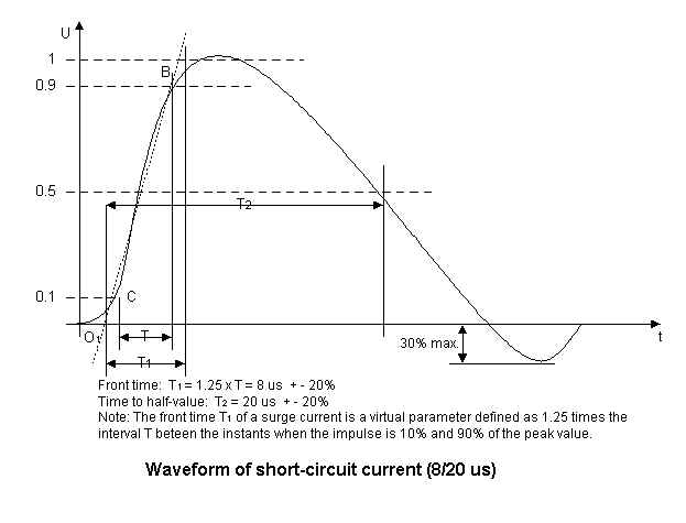
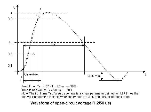
•test generator (combination wave generator, 10/700 µs generator);
•decoupling network/protection devices;
•additional resistors, 10 ? and 40 ? (see B.1 of annex B).
7.2 Test set-up for tests applied to EUT power supply
The surge is to be applied to the EUT power supply terminals via the capacitive coupling network (see figures 6, 7, 8 and 9). Decoupling networks are required in order to avoid possible adverse effects on equipment not under test that may be powered by the same lines and to provide sufficient decoupling impedance to the surge wave so that the specified wave may be developed on the lines under test.
If not otherwise specified the power cord between the EUT and the coupling/decoupling network shall be 2 m in length (or shorter).
To simulate the representative coupling impedances, in some cases additional specified resistors have to be used for the tests (explanations, see B.1 of annex B).
NOTE In some countries (e.g. USA) standards for a.c. lines require the tests according to figures 7 and 9 with a 2 W impedance although this is a more severe test. The general requirement is 10 W.
7.3 Test set-up for tests applied to unshielded unsymmetrically operated interconnection lines
An alternative test set-up (coupling via arrestors) is given in figure 11 for circuits with a higher signal transfer rate. Selection shall be made depending on the capacitive load with respect to the transmission frequency.If not otherwise specified, the interconnection line between the EUT and the coupling/ decoupling network shall be 2 m in length (or shorter).
7.4 Test set-up for tests applied to unshielded symmetrically operated interconnection/telecommunication lines (figure 12)
For balanced interconnection/telecommunication circuits, the capacitive coupling method can normally not be used. In this case, the coupling is performed via gas arrestors (CCITT Recommendation K.17). Test levels below the ignition point of the coupling arrestor (about 300 V for a 90 V arrestor) cannot be specified (except in the case of secondary protection without gas arrestors).
NOTE Two test configurations are to be considered :
• for the equipment level immunity test with only secondary protection at the EUT at a low test level, e.g. 0,5 kV or 1 kV,
• for the system level immunity test with additional primary protection at a higher test level, e.g. 2 kV or 4 kV.
If not otherwise specified the interconnection line between the EUT and the coupling/ decoupling network shall be 2 m in length (or shorter).
7.5 Test set-up for tests applied to shielded lines
Thus the surge is applied to the shields (metallic enclosures) of the EUTs and connected shields of the lines in accordance with figure 13. For shields connected at one end figure 14 applies. For decoupling the connected safety earthwire a safety isolating transformer shall be used. Normally, the maximum length of the specified shielded cable shall be used. With respect to the frequency spectrum of the surge 20 m length of the specified shielded cable shall be used in non-inductively bundled configuration for physical reasons.Rules for application of the surge to shielded lines:
a) Shields earthed at both ends
• the surge injection on the shield shall be carried out according to figure 13.
b) Shields earthed at one end
• the test shall be carried out according to figure 14. The capacitor C represents the cable capacity to earth and the value may be calculated with 100 pF/m. As a representative value 10 nF may be used unless otherwise specified.
The test level applied on shields is the "line-to-earth value" (2 ? impedance).
7.6 Test set-up to apply potential differences
If it is necessary to apply potential differences which simulate voltages that can occur within a system, the tests may be carried out in accordance with figure 13 for systems with shielded lines, shields earthed at both ends, and in accordance with figure 14 for systems with unshielded lines or shielded lines earthed only at one end.
7.7 Other test set-ups
If one of the specified coupling methods in the test set-up cannot be used for functional reasons, alternative methods (suitable for the special case) shall be specified in the dedicated product standard.
7.8 Test conditions
The operational test conditions and the installation conditions shall be in accordance with the product specification and shall include the:
• test configuration (hardware);
• test procedure (software).
B.1 Different source impedances
• the kind of cable/conductor/line (a.c. power supply, d.c. power supply, interconnection, etc.);
•the length of the cables/lines;
•indoor/outdoor conditions;
•application of the test voltage (line to line or lines to earth).
The impedance of 2 W represents the source impedance of the low-voltage power supply network. The generator with its effective output impedance of 2 W is used.
The impedance of 12 W (10 W + 2 W) represents the source impedance of the low-voltage power supply network and earth. The generator with an additional resistor of 10 W in series is used.
The impedance of 42 W (40 W + 2 W) represents the source impedance between all other lines and earth. The generator with an additional resistor of 40 W in series is used.
In some countries (for instance, USA) standards for a.c. lines require the tests according to figures 7 and 9 with a 2 W impedance; this is a more severe test. The general requirement is 10 W.