IMMUNITY TESTING
Dips and Variations Test
Electrical and electronic equipment may be affected by voltage dips, short interruptions or voltage variations of power supply.
Voltage dips and short interruptions are caused by faults in the network, in installations or by a sudden large change of load. In certain cases, two or more consecutive dips or interruptions may occur. Voltage variations are caused by the continuously varying loads connected to the network.
These phenomena are random in nature and can be characterized in terms of the deviation from the rated voltage and duration. Voltage dips and short interruptions are not always abrupt, because of the reaction time of rotating machines and protection elements connected to the power supply network. If large mains networks are disconnected (local within a plant or wide area within a region) the voltage will only decrease gradually due to the many rotating machines, which are connected to the mains networks. For a short period, the rotating machines will operate as generators sending power into the network. Some equipment is more sensitive to gradual variations in voltage than to abrupt change. Most data-processing equipment has built-in power-fail detectors in order to protect and save the data in internal memory so that after the mains voltage has been restored, the equipment will start up in the correct way. Some power-fail detectors will not react sufficiently fast on a gradual decrease of the mains voltage. Therefore, the d.c. voltage to the power-fail detector is activated and data will be lost or distorted. When the mains voltage is restored, the data-processing equipment will not be able to restart correctly before it has been re-programmed.
Consequently, different types of tests are specified to simulate the effects of abrupt change voltage, and, optionally, for the reasons explained above, a type test is specified also for gradual voltage change. This test is to be used only for particular and justified cases.
The EUT is tested for test levels of 30%, 60% and >95% below the rated voltage for the equipment. The duration of the dips/interruptions are 10ms, 100ms and 5000ms respectively. Five dips are performed for each test level at a rate of one dip per minute. The changes in supply voltage occur at zero crossing of the voltage.
The voltages in these tests use the rated voltage for the equipment (UT) as a basis for voltage test level specification.
Where the equipment has a rated voltage range the following shall apply :
Where the equipment has a rated voltage range the following shall apply:
In all other cases, the test procedure shall be applied for both the lower and upper voltages declared in the voltage range.
Voltage dips and short interruptions
The change between UT and the changed voltage is abrupt. The step can start and stop at any phase angles on the mains voltage. The following test voltage levels (in % UT) are used: 0%, 40% and 70%, corresponding to dips and interruptions of 100%, 60% and 30%.
The preferred test levels and durations are given below. A test level of 0% corresponds to a total supply voltage interruption. In practice, a test voltage level from 0% to 20% of the rated voltage may be considered as a total interruption.
Shorter durations in the table, in particular the half-cycle, should be tested to be sure that the equipment under test (EUT) works in its intended performance.
Preferred test levels and durations for voltage dips and short interruptions.
| Test level % UT | Voltage dip and short interruptions % UT | Duration (in period) | ||||||||||||||||
| 0 | 100 |
| ||||||||||||||||
| 40 | 60 | |||||||||||||||||
| 70 | 30 | |||||||||||||||||
| * For 0.5 period, the test shall be made in positive and negative polarity, i.e. starting at 0° and 180° , respectively. | ||||||||||||||||||
| ||||||||||||||||||
Voltage variations (optional)
This test considers a defined transition between rated voltage UT and the changed voltage.
Note – The voltage change takes place over a short period, and may occur due to change of load or stored energy in local power networks.
The preferred duration of the voltage changes and the time for which the reduced voltages are to be maintained are given in the table below. The rate of change of voltage should be constant; however, the voltage may be stepped. The steps should be positioned at zero crossing, and shall be not larger than 10% of UT. Steps under 1% of UT are considered as constant rate of change of voltage.
Timing of short-term supply voltage variations.
| Voltage test level | Time for decreasing voltage | Time at reduced voltage | Time for increasing voltage |
| 40% UT | 2 s ± 20% | 1 s ± 20% | 2 s ± 20% |
| 0% UT | 2 s ± 20% | 1 s ± 20% | 2 s ± 20% |
| X | X | X | |
| Note : X represents an open set of durations and can be given in the product specification. | |||
Voltage Dips and Interruptions TEST SETUP From : From: 61000-4-11 . IEC:2004
7 Test set-up
The test shall be performed with the EUT connected to the test generator with the shortest power supply cable as specified by the EUT manufacturer. If no cable length is specified, it shall be the shortest possible length suitable to the application of the EUT.The test set-ups for the three types of phenomena described in this standard are:
• voltage dips;
• short interruptions;
• voltage variations with gradual transition between the rated voltage and the changed voltage (option).
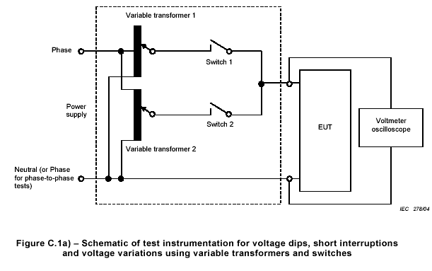
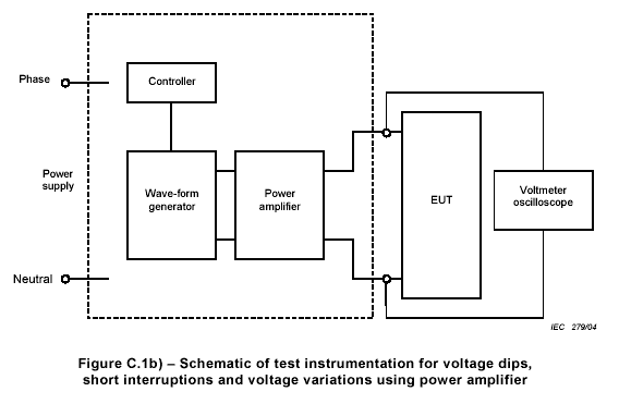
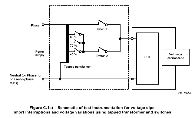
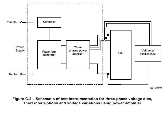
Examples of test set-ups are given in Annex C.
Figure C.1a) shows a schematic for the generation of voltage dips, short interruptions and voltage variations with gradual transition between rated and changed voltage using a generator with internal switching, and Figure C.1b) using a generator and a power amplifier.
Figure C.2 shows a schematic for the generation of voltage dips, short interruptions and voltage variations using a generator and a power amplifier for three-phase equipment.
