IMMUNITY TESTING
Radiated Susceptibility Test
Most electronic equipment is, in some manner, affected by electromagnetic radiation. This radiation is frequently generated by such sources as the small hand-held radio transceivers that are used by operating, maintenance and security personnel, fixed-station radio and television transmitters, vehicle radio transmitters, and various industrial electromagnetic sources.
In recent years there has been a significant increase in the use or radio telephones and other radio transmitters operating at frequencies between 0.8 GHz and 3 GHz. Many of these services use modulation techniques with a non-constant envelope (e.g. TDMA).
In addition to electromagnetic energy deliberately generated, there is also spurious radiation caused by devices such as welders, thyristors, fluorescent lights, switches operating inductive loads, etc. For the most part, this interference manifests itself as conducted electrical interference and, as such, is dealt with in other standards. Methods employed to prevent effects from electromagnetic fields will normally also reduce the effects from these sources.
The electromagnetic environment is determined by the strength of the electromagnetic field (field strength in volts per meter). The field strength is not easily measured without sophisticated instrumentation nor is it easily calculated by classical equations and formulae because of the effect of surrounding structures or the proximity of other equipment that will distort and/or reflect electromagnetic waves.
The EUT is subjected to a field strength of 3 V/m or 10 V/m from 80 MHz to 1000 MHz. This frequency range is 80% amplitude modulated with a 1 kHz sine wave. The signal generator provides the modulated frequency at a step rate of 1% of fundamental to the RF amplifier. The EUT is also subjected to a pulsed 900 MHz field at 200 Hz. The dwell time at each frequency is not less than the time necessary for the EUT to be exercised, and able to respond. The RF amplifier provides the necessary power to the antenna to establish the field levels as monitored by the field probe or power monitor. The anechoic chamber is calibrated according to the criteria as per EN 61000-4-3 for 16 points. The antenna is positioned 3 meters from all four faces of the EUT and is oriented in horizontal and vertical polarization.
The preferential range of test levels is given below.
| Frequency Range: 80 MHz to 1000MHz Test Levels | |
| Level | Test Field Strength V/m |
| 1 | 1 |
| 2 | 3 |
| 3 | 10 |
| X | Special |
| "X" is an open test level. This level may be given in the product specification. | |
Radiated Field TEST SETUP From: 61000-4-3
7 Test set-up
All testing of equipment shall be performed in a configuration as close as possible to the installed case. Wiring shall be consistent with the manufacturer's recommended procedures, and the equipment shall be in its housing with all covers and access panels in place, unless otherwise stated.If the equipment is designed to be mounted in a panel, rack or cabinet, it shall be tested in this configuration.
A metallic ground plane is not required. When a means is required to support the test sample, it shall be constructed of a non-metallic, non-conducting material. However, grounding of housing or case of the equipment shall be consistent with the manufacturer's installation recommendations.
When an EUT consists of floor-standing and table-top components, the correct relative positions shall be maintained.
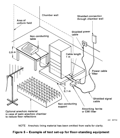
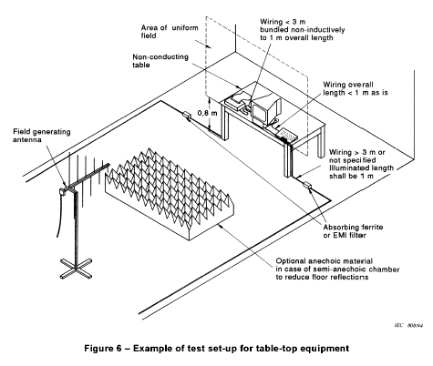
Typical EUT set-ups are shown in figures 5 and 6.

 7.1 Arrangement of table-top equipment
The equipment to be tested is placed in the test facility on a non-conducting table 0,8 m high.NOTE The use of non-conducting supports prevents accidental earthing of the EUT and distortion of the field. To ensure the latter, the support should be bulk non-conducting, rather than an insulating coating on a metallic structure.
The equipment is then connected to power and signal wires according to relevant installation instructions.
7.2 Arrangement of floor-standing equipment
Floor-standing equipment shall be mounted on a non-conducting support 0,1 m above the supporting plane. The use of non-conducting supports prevents accidental earthing of the EUT and distortion of the field. To ensure the latter, the support shall be bulk non-conducting, rather than an insulating coating on a metallic structure. Floor-standing equipment which is capable of being stood on a non-conducting 0,8 m high platform, i.e. equipment which is not too large or heavy, or where its elevation would not create a safety hazard, may be so arranged, if specifically required by the product committees. This variation in the standard method of test shall be recorded in the test report.The equipment is then connected to power and signal wires according to relevant installation instructions.
7.3 Arrangement of wiring
If the wiring to and from the EUT is not specified, unshielded parallel conductors shall be used.Wiring is left exposed to the electromagnetic field for a distance of 1 m from the EUT.
Wiring between enclosures of the EUT shall be treated as follows :
- the manufacturer's specified wiring types and connectors shall be used;
- if the manufacturer's specification requires a wiring length of less than or equal to 3 m, then the specified length shall be used. The wiring shall be bundled low-inductively to 1 m length;
- if the specified length is greater than 3 m, or is not specified, then the illuminated length shall be 1 m. The remainder is decoupled, for instance via lossy r.f. ferrite tubes.
The EMI filtering used shall not impair the operation of the EUT. The method used shall be recorded in the test report.
In one EUT position, the wires shall be arranged parallel to the uniform area of the field to minimize immunity.
All results shall be accompanied by a complete description of the wiring and equipment position and orientation so that results can be repeated.
The bundled length of exposed wiring is run in a configuration which essentially simulates normal wiring; that is, the wiring is run to the side of the EUT, then either up or down as specified in the installation instructions. The horizontal/vertical arrangement helps to ensure worst-case conditions.
7.4 Arrangement of human body-mounted equipment
Human body-mounted equipment may be tested in the same manner as table top items. However, this may involve over-testing or under-testing because the characteristics of the human body are not taken into account. For this reason, product committees are encouraged to specify the use of a human body simulator with appropriate dielectric characteristics.

