IMMUNITY TESTING
Electrical Fast Transient/Burst Test
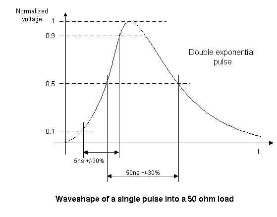
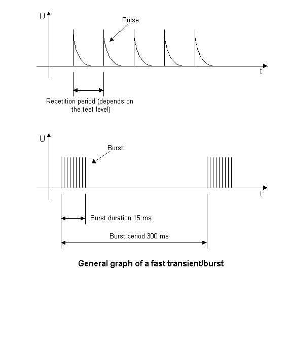
The repetitive fast transient test is a test with bursts consisting of a number of fast transients, coupled into power supply, control and signal ports of electrical and electronic equipment. Significant for the test are the short rise time, the repetition rate and the low energy of the transients.
Test voltages of up to 4 kV in positive and negative polarities are applied to the A/C power leads and up to 2 kV is applied to the I/O cables. The test voltages are at a 5 kHz pulse repetition frequency and applied for 60 seconds to each power supply terminal including protective earth and every combination of these terminals. The coupling clamp is used to apply up to 2 kV to the I/O cables.
The preferential range of test levels for electrical fast transient test, applicable to power supply, protective earth (PE), signal and control ports of equipment is given below.
| Open-circuit output test voltage (± 10%) and repetition rate of the impulses (± 20%) | ||||
| Level | On power supply port, PE | On I/O (Input/Output) signal, data, and control ports | ||
| Voltage Peak kV | Repetition Rate kHz | Voltage Peak kV | Repetition Rate kHz | |
| 1 | 0.5 | 5 | 0.25 | 5 |
| 2 | 1 | 5 | 0.5 | 5 |
| 3 | 2 | 5 | 1 | 5 |
| 4 | 4 | 2.5 | 3 | 5 |
| X | Special | Special | Special | Special |
| "X" is an open level. The level has to be specified in the dedicated equipment specification. | ||||
EFT/Burst TEST SETUP From : 61000-4-4
7 Test set-up
Two different types of tests can be distinguished:
• type tests performed in laboratories;
• post-installations tests performed on equipment in its final installed conditions.
The preferred test method is that of type tests performed in laboratories.
The EUT shall be arranged in accordance with the manufacturer's instructions for installation (if any).
7.1 Test equipment
The test set-up includes the following equipment (see figure 6):
- ground reference plane;
- coupling device (network or clamp);
- decoupling network;
- test generator, including the calibration or measurement means.
7.2 Test set-up for type tests performed in laboratories
7.2.1 Test conditions
The following requirements apply to tests performed in laboratories under the environmental reference conditions outlined in 8.1.
The EUT’s shall be placed on a ground reference plane and shall be insulated from it by an insulating support 0.1 m ± 0.01 m thick.
In the case of table-top equipment, the EUT should be located 0.8 m ± 0.08 m above the ground plane (see figure 7).
The reference ground plane shall be a metallic sheet (copper or aluminum) of 0.25 mm minimum thickness; other metallic materials may be used but they shall have 0.65 mm minimum thickness.
The minimum size of the ground plane is 1 m x 1 m. The actual size depends on the dimensions of the EUT.
The reference ground plane shall project beyond the EUT by at least 0.1 m on all sides.
The reference ground plane shall be connected to the protective earth (“ground” in US terminology).
The EUT shall be arranged and connected to satisfy its functional requirements, according to the equipment installation specifications.
The minimum distance between the EUT and all other conductive structures (e.g. the walls of a shielded room), except the ground plane beneath the EUT, shall be more than 0.5 m.
The EUT shall be connected to the earthing system in accordance with the manufacturer’s installation specifications; no additional earthing connections are allowed.
The connection of the test equipment ground cables to the ground reference plane and all bondings shall provide minimum inductance.
Coupling devices shall be used for the application of the test voltages. They shall be coupled to the lines between the EUT and the decoupling network or between two units of equipment involved in the test.
Using the coupling clamp, the minimum distance between the coupling plates and all other conductive structures, except the ground plane beneath the coupling clamp and beneath the EUT, shall be 0.5 m.
The length of the signal and power lines between the coupling device and the EUT shall be 1 m or less.
If the manufacturer provides a non-detachable supply cable more than 1m long with the equipment, the excess length of this cable shall be gathered into a flat coil with a 0.4 m diameter and situated at a distance of 0.1 m above the ground reference plane. The distance of 1 m or less between EUT and the coupling device shall be maintained.
Examples of the test set-up for laboratory tests are given in figure 7.
7.2.2 Methods of coupling the test voltage to the EUT
The test voltage shall be applied to the following different types of lines or ports of the EUT:
Power supply ports
An example for the test set-up for direct coupling of the EFT/B disturbance voltage via a coupling/decoupling network is given in figure 8.
If the line current is higher than the specified capability of the coupling/decoupling network, i.e. > 100 A, the test voltage shall be applied to the EUT’s through a 33 nF coupling capacitor, according to figure 10.
I/O and communication ports
The examples in figure 7 and figure 9 show how to use the capacitive coupling clamp for application of the disturbance test voltage to the I/O and communication ports.
Earth connections of the cabinets
The test point on the cabinet shall be the terminal for the protective earth conductor.
The test voltage shall be applied to the protective earth (PE) connection by the coupling/decoupling network, see figure 8.
7.3 Test set-up for post-installation tests
These tests are optional, and not mandatory for certification tests; they may be applied only when agreed between manufacturer and customer. It has to be considered that other co-located equipment may be unacceptably affected.
The equipment or system shall be tested in the final installed conditions. Post-installation tests shall be performed without coupling/decoupling networks in order to simulate the actual electromagnetic environment as closely as possible.
If equipment or system other than the EUT are unduly affected during the test procedure, decoupling networks shall be used by agreement between the user and the manufacturer.
7.3.1 Test on power supply ports and on protective earth terminals
Stationary, floor-mounted equipment
The test voltage shall be applied between a reference ground plane and each of the power supply terminals, a.c. or d.c., and on the terminal for the protective or function earth on the cabinet of the EUT.
For the test set-up see figure 10.
A reference ground plane of approximately 1 m x 1 m (as described in 7.2.1) shall be mounted near the EUT and connected to the protective earth conductor at the power supply mains outlet.
The EFT/B-generator shall be located on the reference plane. The length of the “hot wire” from the coaxial output of the EFT/B-generator to the terminals on the EUT should not exceed 1 m. This connection shall be unshielded but well insulated. If a.c./d.c. blocking capacitors are necessary their capacitance shall be 33 nF. All other connections of the EUT should be in accordance with its functional requirements.
Non-stationary mounted EUT, connected to the mains supply by flexible cord and plugs
The test voltage shall be applied between each of the power supply conductors and the protective earth at the power supply outlet to which the EUT is to be connected (see figure 11).
7.3.2 Test on I/O and communication ports
As far as possible, the capacitive coupling clamp shall be used for coupling the test voltage into the lines. However, if the clamp cannot be used due to mechanical problems (size, cable routing) in the cabling, it may be replaced by a tape or a conductive foil enveloping the lines under test. The capacitance of this coupling arrangement with foil or tape should be equivalent to that of the standard coupling clamp.
In other cases, it might be useful to couple the EFT/B-generator to the terminals of the lines via discrete 100 pF capacitors instead of the distributed capacitance of the clamp or of the foil or tape arrangement.
Grounding of the coaxial cable from the test generator shall be made in the vicinity of the coupling point. Application of the test voltage to the connectors (hot wires) of the coaxial or shielded communication lines is not permitted.
The test voltage should be applied in a way that the shielding protection of the equipment will not be reduced. For further explanations, see figure 12.
The test results obtained with the discrete capacitor coupling arrangement are likely to be different from those obtained with the coupling clamp or the foil coupling. Therefore, the test levels specified in clause 5 might be amended by mutual agreement between manufacturer and user in order to take significant installation characteristics into consideration.