IMMUNITY TESTING
Electrostatic Discharge Test
This test relates to equipment, systems, sub-systems and peripherals which may be involved in static electricity discharges owing to environmental and installations conditions, such as low relative humidity, use of low-conductivity (artificial-fiber) carpets, vinyl garments, etc., which may exist in allocations classified in standards relevant to electrical and electronic equipment.
The problem of protecting equipment against the discharge of static electricity has gained considerable importance for manufacturers and users.
The extensive use of microelectronic components has emphasized the need to define the aspects of the problem and to seek a solution in order to enhance products/system reliability.
The problem of static electricity accumulation and subsequent discharges becomes more relevant for uncontrolled environments and the widespread application of equipment and systems in a wide range of industrial plants.
Equipment may also be subjected to electromagnetic energies whenever discharges occur from personnel to nearby objects. Additionally, discharges can occur between metal objects, such as chairs and tables, in the proximity of equipment. However, based on limited experience available to date, it is considered that the tests here may adequately simulate the effects of the latter phenomenon.
The effects of the operator discharge may be a simple malfunction of the equipment or damage of electronic components. The dominant effects can be attributed to the parameters of the discharge current (rise time, duration, etc.).
Electrostatic discharges are applied to the EUT at points and surfaces which are normally accessible to the operator. These discharges are also applied to the metal coupling planes. The voltage levels are increased gradually until the maximum severity level selected is reached. Discharges to the EUT and coupling plane are performed at a minimum of 1 second intervals at each polarity. The minimum of 10 discharges at each polarity are initially performed and increased to 30 discharges as the voltages increase in severity so as to evaluate the performance of the EUT.
The preferential range of test levels for the ESD test is given below.
Testing shall also be satisfied at the lower levels given in the table.
Contact discharge is the preferred test method. Air discharges shall be used where contact discharge cannot be applied. Voltages for each test method are given in the table below. The voltages shown are different for each method due to the differing methods of test. It is not intended to imply that the test severity is equivalent between test methods.
| Contact Discharge | Air Discharge | ||
| Level | Test Voltage kV | Level | Test Voltage kV |
| 1 | 2 | 1 | 2 |
| 2 | 4 | 2 | 4 |
| 3 | 6 | 3 | 8 |
| 4 | 8 | 4 | 15 |
| X | Special | X | Special |
| "X" is an open level. The level has to be specified in the dedicated equipment specification. If higher voltages than those shown are specified, special test equipment may be needed. | |||
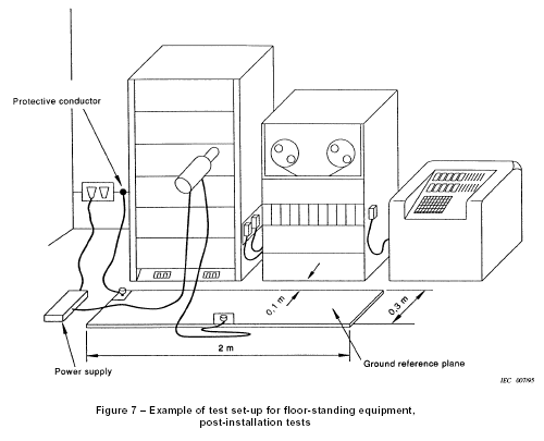
ESD TEST SETUP From: 61000-4-2
Electrical and electronic equipment may be affected by voltage dips, short interruptions or voltage variations of power supply.
Voltage dips and short interruptions are caused by faults in the network, in installations or by a sudden large change of load. In certain cases, two or more consecutive dips or interruptions may occur. Voltage variations are caused by the continuously varying loads connected to the network.
These phenomena are random in nature and can be characterized in terms of the deviation from the rated voltage and duration. Voltage dips and short interruptions are not always abrupt, because of the reaction time of rotating machines and protection elements connected to the power supply network. If large mains networks are disconnected (local within a plant or wide area within a region) the voltage will only decrease gradually due to the many rotating machines, which are connected to the mains networks. For a short period, the rotating machines will operate as generators sending power into the network. Some equipment is more sensitive to gradual variations in voltage than to abrupt change. Most data-processing equipment has built-in power-fail detectors in order to protect and save the data in internal memory so that after the mains voltage has been restored, the equipment will start up in the correct way. Some power-fail detectors will not react sufficiently fast on a gradual decrease of the mains voltage. Therefore, the d.c. voltage to the power-fail detector is activated and data will be lost or distorted. When the mains voltage is restored, the data-processing equipment will not be able to restart correctly before it has been re-programmed.
Consequently, different types of tests are specified to simulate the effects of abrupt change voltage, and, optionally, for the reasons explained above, a type test is specified also for gradual voltage change. This test is to be used only for particular and justified cases.
The EUT is tested for test levels of 30%, 60% and >95% below the rated voltage for the equipment. The duration of the dips/interruptions are 10ms, 100ms and 5000ms respectively. Five dips are performed for each test level at a rate of one dip per minute. The changes in supply voltage occur at zero crossing of the voltage.
The voltages in these tests use the rated voltage for the equipment (UT) as a basis for voltage test level specification.
- contact discharge to the conductive surfaces and to coupling planes;
- air discharge at insulating surfaces.
- type (conformance) tests performed in laboratories;
- post installation tests performed on equipment in its final installed conditions.
7.1 Test set-up for tests performed in laboratories
The following requirements apply to tests performed in laboratories under environmental reference conditions outlined in 8.1.
A ground reference plane shall be provided on the floor of the laboratory. It shall be a metallic sheet (copper or aluminum) of 0,25 mm minimum thickness; other metallic materials may be used but they shall have at least 0,65 mm minimum thickness.
The minimum size of the reference plane is 1 m2, the exact size depending on the dimensions of the EUT. It shall project beyond the EUT or coupling plane by at least 0,5 m on all sides, and shall be connected to the protective grounding system.
Local safety regulations shall always be met.
The EUT shall be arranged and connected according to its functional requirements.
A distance of 1 m minimum shall be provided between the equipment under test and the walls of the laboratory and any other metallic structure.
The EUT shall be connected to the grounding system, in accordance with its installation specifications. No additional grounding connections are allowed.
The positioning of the power and signal cables shall be representative of installation practice.
The discharge return cable of the ESD generator shall be connected to the ground reference plane. The total length of this cable is in general 2 m.
In cases where this length exceeds the length necessary to apply the discharges to be selected points, the excess length shall, where possible, be placed non-inductively off the ground reference plane and shall not come closer than 0,2 m to other conductive parts in the test set-up.
The connection of the earth cables to the ground reference plane and all bondings shall be of low impedance, for example by using clamping devices for high frequency applications.
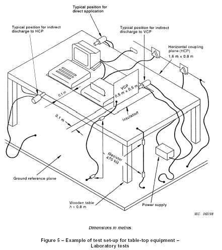
Where coupling planes are specified, for example to allow indirect application of the discharge, they shall be constructed from the same material type and thickness as that of the ground reference plane, and shall be connected to the GRP via a cable with a 470 kW resistor located at each end. These resistors shall be capable of withstanding the discharge voltage and shall be insulated to avoid short circuits to the GRP when the cable lies on the GRP.
Additional specifications for the different types of equipment are given below.
7.1.1 Table-top equipment
The test set-up shall consist of a wooden table, 0,8 m high, standing on the ground reference plane.
A horizontal coupling plane (HCP), 1,6 m × 0,8 m, shall be placed on the table. The EUT and cables shall be isolated from the coupling plane by an insulating support 0,5 mm thick.
If the EUT is too large to be located 0,1 m minimum from all sides of the HCP, an additional, identical HCP shall be used, placed 0,3 m from the first, with the short sides adjacent. The table has to be enlarged or two tables may be used. The HCPs shall not be bonded together, other than via resistive cables to the GRP.
Any mounting feet associated with the EUT shall remain in place.
An example of the test set-up for table-top equipment is given in figure 5.
7.1.2 Floor-standing equipment
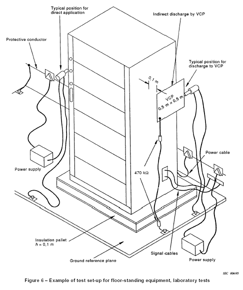
The EUT and cables shall be isolated from the ground reference plane by an insulating support about 0,1 m thick.
An example of the test set-up for floor-standing equipment is given in figure 6.
Any mounting feet associated with the EUT shall remain in place.
7.1.3 Test method for ungrounded equipment
The test method described in this subclause is applicable to equipment or part(s) of equipment whose installation specifications or design preclude connection to any grounding system. Equipment, or parts thereof, includes portable, battery-operated and double-insulated equipment (class II equipment).
Rationale: Ungrounded equipment, or ungrounded part(s) of equipment, cannot discharge itself similarly to class I mains-supplied equipment. If the charge is not removed before the next ESD pulse is applied, it is possible that the EUT or part(s) of the EUT be stressed up to twice the intended test voltage. Therefore, double-insulated equipment could be charged at an unrealistically high charge, by accumulating several ESD discharges on the capacitance of the class II insulation, and then discharge at the breakdown voltage of the insulation with a much higher energy.
The general test set-up shall be identical to the ones described in 7.1.1 and 7.1.2 respectively.
To simulate a single ESD event (either by air or by contact discharge), the charge on the EUT shall be removed prior to each applied ESD pulse.
The charge on the metallic point or part to which the ESD pulse is to be applied, for example, connector shells, battery charge pins, metallic antennae, shall be removed prior to each applied ESD test pulse.
When one or several metallic accessible parts are subject to the ESD test, the charge shall be removed from the point where the ESD pulse is to be applied, as no guarantee can be given about the resistance between this and other accessible points on the product.
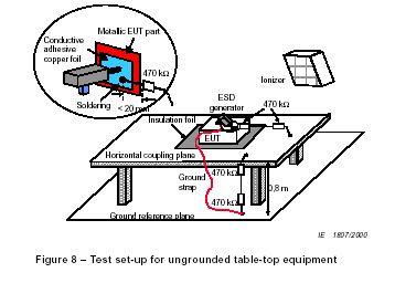
A cable with 470 kW bleeder resistors, similar to the one used with the horizontal and vertical coupling planes, shall be used; see 7.1.
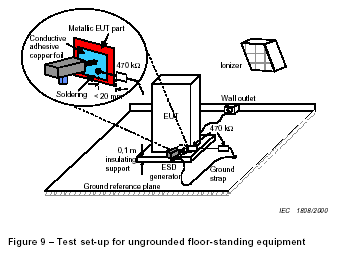
As the capacitance between EUT and HCP (table-top) and between EUT and GRP (floorstanding) is determined by the size of the EUT, the cable with bleeder resistors may remain installed during the ESD test when functionally allowed. In the discharge cable, one resistor shall be connected as close as possible, preferably less than 20 mm from the EUT test point. The second resistor shall be connected near the end of the cable attached to the HCP for table-top equipment (see figure 8), or GRP for floor-standing equipment (see figure 9).
The presence of the cable with the bleeder resistors can influence the test results of some equipment. In case of dispute, a test with the cable disconnected during the ESD pulse takes precedence over the test with the cable installed during the test, provided that the charge has sufficiently decayed between the successive discharges.
As an alternative, the following options can be used :
- the time interval between successive discharges shall be extended to the time necessary to allow natural decay of the charge from the EUT;
- a carbon fibre brush with bleeder resistors (for example, 2 × 470 k.) in the grounding cable;
- an air-ionizer to speed-up the "natural" discharging process of the EUT to its environment.
The ionizer shall be turned off when applying an air-discharge test. The use of any alternative method shall be reported in the test report.
NOTE : In case of dispute concerning the charge decay, the charge on the EUT can be monitored by a noncontacting electric field meter. When the charge has decayed below 10 % of the initial value, the EUT is considered to be discharged.
The tip of the ESD generator shall be held normal (perpendicular) to the surface of the EUT.
7.1.3.1 Table-top equipment
For table-top equipment, the EUT is placed on the horizontal coupling plane on top of the insulating foil (0,5 mm thick), as described in 7.1.1 and figure 5.
When a metallic accessible part, to which the ESD pulse is to be applied, is available on the EUT, this part shall be connected to the HCP via the cable with bleeder resistors; see figure 8.
7.1.3.2 Floor-standing equipment
Floor-standing equipment without any metallic connection to the ground reference plane shall be installed similarly to 7.1.2 and figure 6.A cable with bleeder resistors shall be used between the metallic accessible part, to which the ESD pulse is to be applied, and the ground reference plane (GRP); see figure 9
7.2 Test set-up for post-installation tests
These tests are optional, and not mandatory for certification tests; they may be applied only when agreed between manufacturer and customer. It has to be considered that other co-located equipment may be unacceptably affected.
The equipment or system shall be tested in its final installed conditions.
In order to facilitate a connection for the discharge return cable, a ground reference plane shall be placed on the floor of the installation, close to the EUT at about 0,1 m distance. This plane should be of copper or aluminium not less than 0,25 mm thick. Other metallic materials may be used, providing the minimum thickness is 0,65 mm. The plane should be approximately 0,3 m wide, and 2 m in length where the installation allows.
This ground reference plane should be connected to the protective earthing system. Where this is not possible, it should be connected to the earthing terminal of the EUT, if available.
The discharge return cable of the ESD generator shall be connected to the reference plane at a point close to the EUT. Where the EUT is installed on a metal table, the table shall be connected to the reference plane via a cable with a 470 kW resistor located at each end, to prevent a build-up of charge.
An example of the set-up for post-installation tests is given in figure 7.
