IMMUNITY TESTING
Magnetic Field Test
The magnetic fields to which equipment is subjected may influence the reliable operation of equipment and systems.
These tests are intended to demonstrate the immunity of equipment when subjected to power frequency magnetic fields related to the specific locations and installation condition of the equipment (e.g. proximity of equipment to the disturbance source). The power frequency magnetic field is generated by power frequency current in conductors or, more seldom, from other devices (e.g. leakage of transformers) in the proximity of equipment.
The EUT is subjected to a continuous magnetic field of 3 A/m or 10 A/m by use of an induction coil of standard dimensions 1m x 1m. The induction coil is then rotated by 90° in order to expose the EUT to the test field with different orientations. Three orthogonal planes are tested. The dwell time at each frequency is not less than the time necessary for the EUT to be exercised, and able to respond.
The preferential range of test levels, respectively for continuous and short duration application of magnetic field, applicable to distribution networks at 50 Hz and 60 Hz, is given below.
The magnetic field strength is expressed in A/m; 1 A/m corresponds to a free space induction of 1.26 µT.
Test Levels for continuous field.
| Level | Magnetic field strength A/m |
| 1 | 1 |
| 2 | 3 |
| 3 | 10 |
| 4 | 30 |
| 5 | 100 |
| X | Special |
| "X" is an open level. This level can be given in the product specification. | |
Test Levels for short duration: 1 s to 3 s.
| Level | Magnetic field strength A/m |
| 1 | n.a. |
| 2 | n.a. |
| 3 | n.a. |
| 4 | 300 |
| 5 | 1000 |
| X | Special |
"X" is an open level. This level can be given in the product specification. n.a. = not applicable | |
Magnetic Field TEST SETUP From : 61000-4-8 . IEC:1993 +A1:2000
7 Test set-up
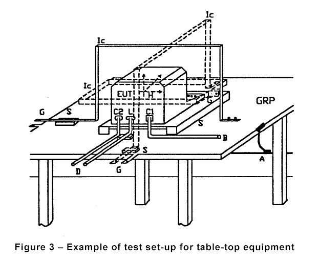
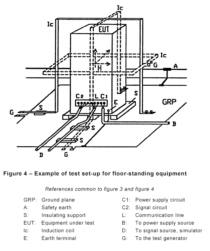
The test set-up comprises the following components:• ground (reference) plane (GRP);
• equipment under test (EUT);
• induction coil;
• test generator
• Precautions shall be taken if the test magnetic field may interfere with the test instrumentation and other sensitive equipment in the vicinity of the test set-up.Examples of test set-ups are given in the following figures:
Figure 3: Example of test set-up for table-top equipment

Figure 4: Example of test set-up for floor-standing equipment

7.1 Ground (reference) plane
The ground plane (GRP) shall be placed in the laboratory; the EUT and auxiliary test equipment shall be placed on it and connected to it.The ground plane shall be a non-magnetic metal sheet (copper or aluminium) of 0,25 mm thickness; other metals may be used but in this case they shall have 0,65 mm minimum thickness.
The minimum size of the ground plane is 1 m × 1 m.
The final size depends on the dimensions of the EUT.
The ground plane shall be connected to the safety earth system of the laboratory.
7.2 Equipment under test
The equipment is configured and connected to satisfy its functional requirements. It shall be placed on the GRP with the interposition of a 0,1 m thickness insulating support (e.g. dry wood).The equipment cabinets shall be connected to the safety earth directly on the GRP via the earth terminal of the EUT.
The power supply, input and output circuits shall be connected to the sources of power supply, control and signal.
The cables supplied or recommended by the equipment manufacturer shall be used. In absence of any recommendation, unshielded cables shall be adopted, of a type appropriate for the signals involved. All cables shall be exposed to the magnetic field for 1 m of their length.
The back filters, if any, shall be inserted in the circuits at 1 m cable lengths from the EUT and connected to the ground plane.
The communication lines (data lines) shall be connected to the EUT by the cables given in the technical specification or standard for this application.
7.3 Test generator
The test generator shall be placed at less than 3 m distance from the induction coil.One terminal of the generator shall be connected to the ground plane as far as used.
7.4 Induction coil
The induction coil, of the type specified in 6.2.1, shall enclose the EUT placed at its centre. Different induction coils may be selected for testing in the different orthogonal directions, according to the general criteria specified in 6.2.1 a) and b).
Induction coils used in the vertical position (horizontal polarization of the field) can be bonded (at the foot of one vertical conductor) directly to the ground plane, which represents the low side of the coil, as a part of it. In this case, 0,1 m minimum distance from EUT to the ground plane is sufficient.
The induction coil shall be connected to the test generator in the same way as for the calibration procedure specified in 6.2.2.
The induction coil selected for the tests shall be specified in the test plan.

